HoloM3D
Personal projects | | Links: Read the report
Overview
Type : School, Bachelor thesis
Technology : C++, OpenGL, DirectX11, HoloLens
Project introduction
HoloM3D project presentation
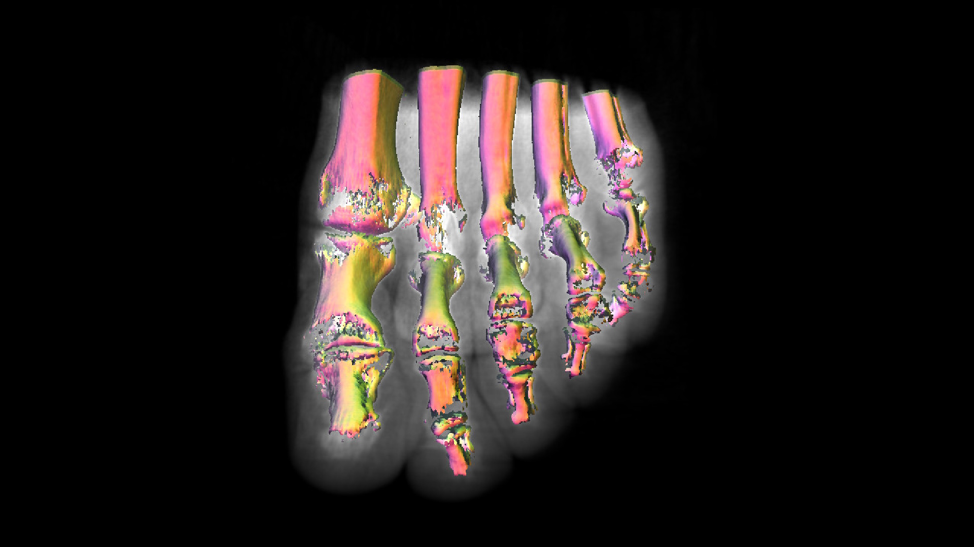
The primary aim of the HoloM3D project revolves around leveraging HoloLens headsets to introduce a novel approach for visualizing a 3D matrix designed for surgeons during pre-operative sessions. Surgeons heavily rely on medical imaging to comprehend their patients’ conditions; however, they often encounter unforeseen challenges during operations due to variations in the positioning of organs and blood vessels. Medical devices like MRI or CT-Scan typically generate a 3D matrix comprised of intensity points. The accurate representation of this matrix holds immense significance in providing crucial information for surgeons. The integration of innovative technologies such as Microsoft’s HoloLens aims to present these matrices in a fresh and enhanced manner, potentially revolutionizing the visualization process for medical professionals.
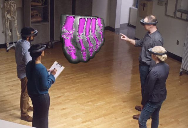
Illustration showing an overview of the HoloM3D project
This collaborative project involves CHUV, HES-SO Valais, and He-Arc. The Valais team’s role includes processing 3D matrices sourced from CHUV to create a comprehensive super-matrix amalgamating various medical imaging matrices. Meanwhile, He-Arc is responsible for managing the presentation of this 3D matrix through HoloLens headsets.
To visualize the 3D matrix, we employ an algorithm derived from the volume rendering family, projecting 3D data volumes into 2D. While volume ray casting yields superior results, it demands significant time and resources. Unfortunately, employing this algorithm directly on HoloLens proves impractical due to its resource-intensive nature.
To address this challenge, we’ve devised a solution using remote computing. The matrix rendering process will occur on a server equipped with a dedicated GPU. Each computed frame will be transmitted to the headset via WiFi for display. Furthermore, the server will facilitate the sharing of holographic data among multiple HoloLens headsets.
In summary, the HoloM3D project unfolds through five key stages:
The CHUV medical team conducts diverse medical examinations on a patient, encompassing MRI, PET-Scan, and CT-Scan. These examinations generate three distinct 3D data matrices.
The He-Vs team takes charge of processing these matrices. Initially, they merge the three matrices into a unified whole and subsequently conduct 3D segmentation to highlight areas of significance.
Following this, the consolidated matrix undergoes further handling by the He-Arc team. A specialized program on a dedicated server loads and employs the volume ray casting algorithm for rendering. This rendering process occurs on the server and is transmitted to the HoloLens via Wifi using remote computing.
The HoloLens displays the rendered output received from the server and continuously relays its spatial positioning data back to the server, performing this operation at a minimum rate of 60 times per second.
Surgeons actively utilize HoloLens headsets during pre-operative sessions to gain deeper insights into patient data and provide essential feedback, enhancing their understanding and decision-making processes.
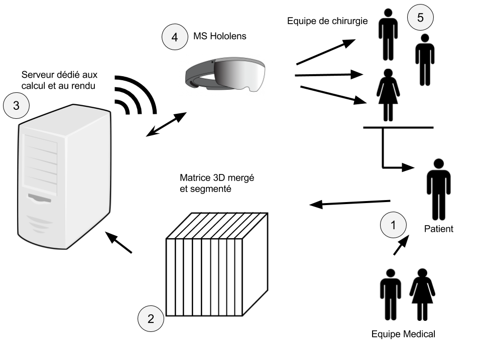
Illustration summarizing the five stages of the HoloM3D project
Goal of the Bachelor’s thesis
In this project, my responsibility centered on refining the rendering of the matrix in the preliminary stage. During my bachelor’s project, my primary focus revolved around implementing volume ray casting rendering on the designated server. Meanwhile, a master’s student took charge of establishing communication between the server and the HoloLens, along with facilitating the matrix sharing among headsets through remote computing.
The core objectives of the bachelor’s project aimed to achieve volume ray casting with false-color thresholding for densities while ensuring a high refresh rate of over 60 frames per second. Secondary goals were aimed at enhancing rendering quality, encompassing the incorporation of realistic textures, materials, and algorithm optimization.
Following the completion of our individual projects, the plan was to integrate our work into a unified, functional program. Unfortunately, unforeseen personal challenges significantly hindered the master’s student from delivering their portion of the work, causing an unexpected deviation from the initial timeline. Consequently, the bachelor’s project underwent adaptations to accommodate the inclusion of the master’s student’s work. Apart from refining matrix rendering, our team had to incorporate integration with the HoloLens remote computing program.
Theoretical concepts
Within this segment, I will elaborate extensively on the mechanics behind the volume ray casting algorithm, along with providing detailed insights into the functionalities of graphics APIs.
Volume ray casting
Volume ray casting or volume ray tracing serves the purpose of visualizing either a 2D image of a data matrix or a 3D volume of data. It’s important to note that this method differs from conventional ray tracing. Unlike traditional ray tracing, where the ray halts at the surface of an object, volume ray casting involves the ray passing through the volume, gathering samples along its path. Notably, this technique does not generate secondary rays. The algorithm comprises four distinct steps elucidated in the diagram below.
Ray tracing: Each pixel within the image initiates a ray traversing through the volume, akin to the process in ray tracing. Typically, the volume is assumed to be a cube, allowing the ray to terminate when it exceeds the boundaries of the cube.
Sampling: As the ray progresses through the volume, it establishes sampling points at regular intervals, directly influencing the final rendering’s quality. These points, in general, are not necessarily aligned with the voxels within the volume, necessitating interpolation techniques to recover the sampled values.
Shading: At each sampled point, a threshold or transfer function is utilized to compute the pixel color. Additionally, the gradient, depicting the orientation within the volume, is calculated. The point’s overall color is determined by computing the diffuse illumination gradient.
Compositing: Following the color calculation for all samples, the pixel’s value is determined by combining the various sample colors. The method of color summation can vary based on the desired rendering outcome. Different approaches are adopted depending on the intended rendering effect.
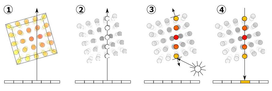
Diagram illustrating the four stages of volume ray tracing (1) Ray casting (2) Sampling (3) Shading (4) Compositing
Face culling
Within a graphics API, the cull mode serves the purpose of selecting specific faces of a 3D object for rendering while discarding others. It provides the flexibility to opt for rendering solely the front (visible) or back (non-visible) faces of the object, or alternatively, no faces at all, as per the needs of the application. This functionality aids in optimizing graphics performance by avoiding the rendering of faces that aren’t visible, effectively reducing the workload on the graphics processor.
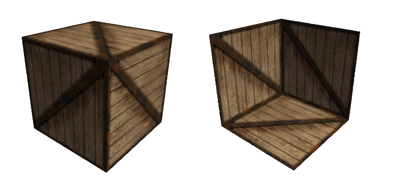
Capture of a textured cube rendered with both face culling modes, on the left in backface mode and right in frontface mode
Volume ray casting - Ray direction
In determining the direction of the rays emitted during the initial stage of the volume ray casting algorithm, there exist several approaches. I will outline the technique utilized for this particular project.
The employed method relies on the premise that the color of the pixel within the cube corresponds to its spatial location. Essentially, the eight points comprising the cube possess coordinates ranging between (0,0,0) and (1,1,1), as depicted in the initial cube in the image below. When this cube is exhibited on the screen, each colored pixel constituting the cube concurrently represents its spatial positioning. Hence, this cube serves as a representation of the matrix within the spatial domain.
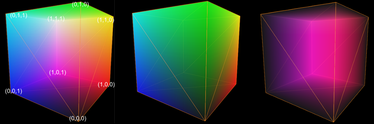
Image showing the three calculated textures (1) backface (2) frontface (3) direction
Determining the ray directions involves a multi-step process. Initially, we render the cube while setting the cull mode to backface, capturing and storing this rendering in a texture. Subsequently, we re-render the same cube, modifying solely the cull mode to frontface, and similarly record this rendering into another texture. Once both textures (backface and frontface) are generated, they become instrumental in computing the ray direction within the volume.
The direction calculation is straightforward; it involves subtracting the two textures we’ve obtained. Given that these textures encapsulate the spatial positions of each pixel (as represented by the pixel’s color), subtracting the positions allows us to derive the directional vector between these respective points. As illustrated in the diagram, the blue texture signifies the frontface texture, while the green indicates the backface texture. The subtraction operation between these points yields the direction of the resultant red vector. Consequently, the texture resulting from this computation contains the direction associated with every ray for each pixel within the cube.
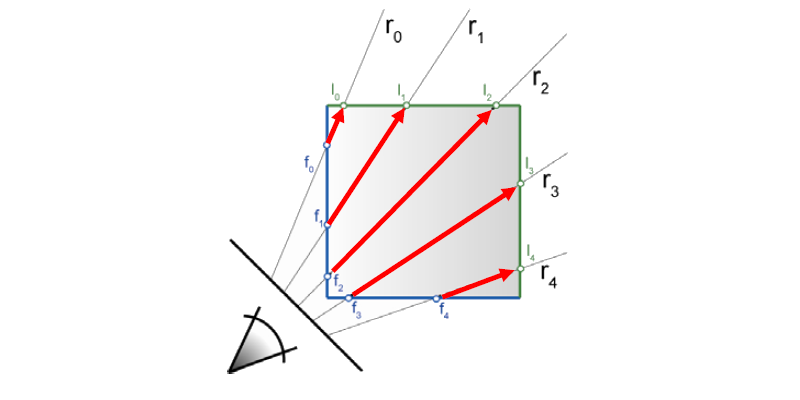
Diagram illustrating ray direction calculation
Implementation
OpenGL
For the initial rendering of the matrix, I opted for OpenGL as the graphics API, given its similarity to WebGL, which we had covered in class. The program was crafted in accordance with the initial specifications and featured the following functionalities:
- A threshold rendering mode, wherein the matrix’s sample values are compared to a set threshold. Upon surpassing this threshold, the algorithm halts, and the lighting at that specific point is calculated.
- An “X-Ray” rendering mode, where the cumulative values of all sample points along a ray are summed. Once the ray completes traversing the matrix, this sum is divided by the number of points to generate a coherent rendering.
- In oversampling mode, neighboring values are retrieved and averaged when the matrix undergoes resampling. This technique enhances rendering smoothness while reducing texture noise. However, it substantially escalates matrix access, incurring significant costs.
Initially developed using OpenGL, an issue emerged when attempting to share the OpenGL program’s rendering with the remote computing program running on DirectX. As a resolution, the decision was made to transition the rendering from OpenGL to DirectX, aiming to simplify the process and expedite the prototype’s development. Consequently, I delved into learning DirectX on-the-go and subsequently reconfigured the matrix rendering program a second time, specifically for DirectX 11. While the program itself may not hold intrinsic value, it served as a pivotal foundation for comprehending the mechanics of DirectX 11 and facilitated the integration of rendering into the remote computing program.
DirectX
The DirectX rendering iteration adheres to the same foundational principles as the initial version. It preserves the threshold and x-ray rendering modes, while opting to forego the oversampling mode due to its resource-intensive nature, unsuitable for the HoloLens environment that necessitates consistent high frame rates.
DirectX and OpenGL exhibit divergent approaches within the graphics API domain. OpenGL offers a more user-friendly experience as numerous functionalities are automated, shielding developers from intricate processes. Conversely, DirectX provides comprehensive accessibility, granting developers control over all aspects, although requiring them to manually execute operations. Despite these differences, achieving similar outcomes is feasible with both APIs.
Remote Computing
As the Master’s student didn’t furnish a DirectX rendering program, we resorted to utilizing the remote computing example program supplied by Microsoft in the SDK. To generate the rendering transmitted to the headset, two images are necessary for stereoscopic rendering—one for each eye. These images entail slightly different projection matrices to achieve stereoscopy. Consequently, the drawing function needs to be executed twice, correspondingly for each matrix, ensuring that the rendering appears accurately in both eyes of the headset.
Results
OpenGL
To view the OpenGL rendering outcomes, refer to the video showcasing various rendering modes using threshold values and oversampling.
HoloLens
For a glimpse of the rendered content in the headset, you may watch the video below. Please note that replicating the 3D effect of HoloLens in both images and videos poses significant challenges.
Conclusion
Initially, the objective of this Bachelor’s thesis centered around creating a ray-traced volume rendering of a 3D matrix for the HoloM3D project. Due to challenges faced by the Master’s student and technical impediments, the objectives of the Bachelor’s thesis were altered to encompass integration with the remote computing program. Ultimately, the project significantly surpassed its initial goals by successfully rendering the matrix in OpenGL, DirectX, and seamlessly integrating it with HoloLens remote computing. Throughout this process, we also acquired expertise in DirectX and HoloLens-related technologies.
The current pre-prototype functions effectively, enabling users to visualize the 3D matrix in real-time through the headset. This pre-prototype validates the project’s feasibility. This effort has not only added substantial tangibility to the HoloM3D project but also paves the way for further advancements by other contributors.